Corrections
Technical Drawing 101 with AutoCAD 2015
A Multidisciplinary Curriculum for the First Semester
- View Corrections
- Submit Corrections
Corrections
- Chapter 2 Page 65
In sketching problem number 2, there is a line appearing as visible line on the right side of the object that should have been displayed as a grid line.
- Chapter 3 Page 78
Figure 3.19 should show the Architects 1/4 scale instead of the Engineers 10 scale. The correct art is shown in the Instructor's powerpoint slide show for Chapter 3.
- Chapter 4 Page 134
Step 3: If Dynamic Input is off, typing 8,5 in Step 3 works correctly because typing 8,5 defines the second point of the arc as an absolute coordinate (one that is relative to 0,0 - which is what the instructions indicate we are defining). However, if Dynamic input is toggled on, the user must type #8,5 in order to draw to the absolute coordinate located at 8,5. If you type 8,5 with Dynamic Input toggled on, the next point will be located (in error) 8 units on the X axis and 5 units on the Y axis relative to the first point – which is not what the authors intended in this example – so the mistake is ours.
In the instructions for the book, the authors tell users of the book to turn Dynamic Input on, for this reason, the authors should have written that in Step 3 that the user should enter #8,5 instead of 8,5 to define the second point as an absolute coordinate.
Note: To draw the arc shown in the view on Figure 4.50(b), the user would select the Arc command’s Start, End, Radius option and pick the (Start) point at the end of the line as shown in the figure, next, the user would select the endpoint of the line shown for the second (End) pick, and then type 2 and Enter to define the arc’s radius.
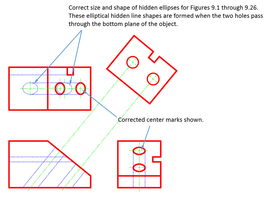
- Chapter 9 Page 1
On the top view shown in Figures 9.1 through 9.26, the ellipses (shown as hidden lines) that represent the shapes created when the two holes pass through bottom plane of object, should be longer along their X-Y axes.
See the attached figure showing the corrected ellipses. Note: The narrower ellipses shown in Figure 9.1 through 9.26 of the textbook, though incorrect, do not impact the construction of the Auxiliary View of Plane A because these ellipses do not lie on plane A (so they are not used in the projection of the geometry of Plane A).
Submit Corrections
Your information will remain private. We will only use your information if we need to contact you for further details regarding the correction you submit.