Corrections
Parametric Modeling with Autodesk Inventor 2016
- View Corrections
- Submit Corrections
Corrections
- Chapter 1 Page 13
The first paragraph "Create" should be "3D Model".
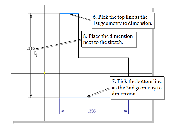
- Chapter 2 Page 14
Step numbers do not correlate with those shown in top image.
- Chapter 2 Page 18
The fourth bullet point should be a new paragraph:
The Free Orbit command allows us to:
- Orbit a part or assembly in the graphics window. Rotation can be around the center mark, free in all directions, or around the X/Y-axes in the 3D-Orbit display.
- Reposition the part or assembly in the graphics window.
- Display isometric or standard orthographic views of a part or assembly.
The Free Orbit tool is accessible while other tools are active. Autodesk Inventor remembers the last used mode when you exit the Orbit command.
- Chapter 2 Page 21
"2D View" should be "Look At"
- Chapter 2 Page 22
"2D View" should be "Look At"
- Chapter 2 Page 25
The Fifth paragraph "Wireframe with Hidden-Edge Display" should be italic, not bold. It should also say "Wireframe with Hidden Edges"
- Chapter 2 Page 25
In the fifth paragraph the description for this model display is not accurate.
Wireframe with Hidden-Edge:
The Wireframe with Hidden-Edge option can be used to generate an image of the 3D object with all the back lines shown as hidden-lines.
- Chapter 2 Page 25
In the sixth paragraph should read:
Besides the above basic display modes, we can also choose orthographic view or perspective view of the display. Click on the triangle icon next to the display mode button on the View toolbar, as shown in the figure.
- Chapter 2 Page 26
Step 2. "Select face, workplane, ...." this text does not match the message from the software.
In the Status Bar area, the message “Select plane to create sketch or an existing sketch to edit.” is displayed.
- Chapter 2 Page 30
Step 13. "Part Features" should be "3D Model" and "releasing" should be "clicking."
- Chapter 2 Page 31
Step 17. should read:
Click on the Direction icon and choose Direction 2 to set the extrusion direction downward as shown.
- Chapter 2 Page 32
Step 2. "Select face, workplane, ...." this text does not match the message from the software.
In the Status Bar area, the message “Select plane to create sketch or an existing sketch to edit.” is displayed.
- Chapter 2 Page 33
Step 8 "Part Features" should be "3D Model"
- Chapter 2 Page 37
Step 8 "releasing" should be "clicking"
- Chapter 3 Page 8
Step 2 “Front Plane” should be replaced with “XY Plane”.
- Chapter 3 Page 9
“GRID Intervals Setup” should be “GRID Display Setup”.
Step 3. Ignore the text “In the Document Settings dialog box,”
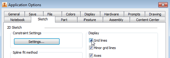
Step 5. After clicking OK, the Grid is NOT displayed:
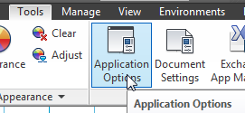
Step 5-1, Switch on the Grid lines in the Application Options as shown.
- Chapter 3 Page 17
Replace “Part Features” with “3D Model”.
- Chapter 3 Page 18
Replace “Select face, workplane, sketch or sketch geometry” with “Select plane to create sketch or an existing sketch to edit”.
- Chapter 3 Page 19
Step 11. Ignore “in the popup menu to end the Sketch mode”.
- Chapter 3 Page 20
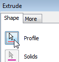
Step 13 “Create Features” toolbar should be “Create” and ”right side” should be “right”.
- Chapter 3 Page 20
Step 14. The Profile button is pressed down as show here:
- Chapter 3 Page 24
Step 11. “Create Features” toolbar should be “Create” and ”right side” should be “right”.
- Chapter 3 Page 25
Step 1 should say: In the Create toolbar, select the Hole command by releasing the left-mouse-button on the icon.
- Chapter 4 Page 7
Step 7 replace “model create” with “3D Model”.
- Chapter 5 Page 5
Step 7 should read: ..... A Help-tip box appears next to the cursor, and a brief description of the command is displayed at the bottom of the drawing screen: “Creates Straight line and arcs.”
- Chapter 5 Page 9
Step 9 should read (For example, “if” the dimension value is 2.20,
soenter 3.0 in the text box area.)- Chapter 5 Page 14
Last sentence should read – In parametric modeling, it is desired to create fully constrained sketches
- Chapter 6 Page 17
Step 5 should read : On your own, complete the sketch by adjusting the dimensions to the desired values as shown below. (Hint: Change the larger values first.)
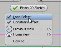
- Chapter 6 Page 23
step 5-1, Right-click once to bring up the option menu and activate "select loop” as shown.
Submit Corrections
Your information will remain private. We will only use your information if we need to contact you for further details regarding the correction you submit.